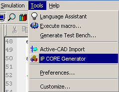
The IP CORE Generator Installation program adds a new function
to Active-HDL 4.2 by selecting: TOOLS -> IP CORE Generator.
This will run the wizard in a standard Active-HDL window.
Figure
1. Run
IP CORE Generator from Active-HDL Tools menu
This option will open the IP CORE Generator in the Active-HDL
environment:
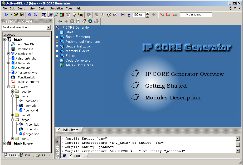
Figure 2. IP CORE Generator opened in Active-HDL environment
You have simple access to three documentation links:
| IP CORE Generator Overview | Short information on the IP CORE Generator |
| Getting Started | Documentation about starting, using and generating modules with the IP CORE Generator |
| Modules Description | Each module has a short description about behavior, input name format, input data range |
- books(group),
- documents(generated modules),
- plus(expand tree),
- minus(collapse tree).
|
|
Basic
|
Arithmetical
Functions
|
Sequential
Logic
|
Memory
Blocks
|
Filters
|
Code
Converters
|
|
|
|
|
shift register, simple register-latch, simple register-FlipFlop |
Fifo-Lifo |
FIR gen., MinMax |
hot2gray, hot2johnson, bcd2 7-reg, bcd2bin bin2 7-reg, bin2bcd, bin2gray, bin2hot, bin2johnson, gray2hot, gray2bin, gray2johnson, johnson2bin, johnson2hot, johnson2gray |
The IP CORE Generator browser gives you a direct link to
ALATEK website, where you can find new version
updates of the IP CORE Generator product and links to IP CORE
pages or web based tools.
See IP CORE Generator browser at figure 2:
(In this example we have just click on Arithmetical
Functions book/folder)
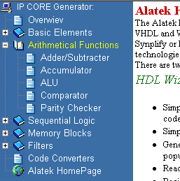
Figure 3.
IP CORE Generator browser
B) Graphical Module Representation;
You may select a module name on the left of the browser to display a graphic al representation of the requested module. We will use Accumulator module for generate presentation. The figure below shows the standard input and configuration objects:
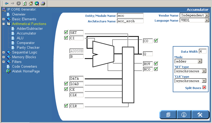
Figure 4: Accumulator module - view
The IP CORE Generator view design was split into three thematic sections, which allows for the best graphical readability. The following description explains the sections of Figure 4:
Section 1:
This section is dedicated to enter Entity/Module Name, and Architecture
Name for the VHDL
language. The reserved words list depends on selected the Language
Name. Most of the available
modules were designed as vendor independent. Because
of this, the Vendor Name list often contains the Independent
option.
Section 2:
In
this section, you
may enter
the names of input and output ports. Additionally,
some ports have a check
box to include or disable it during
the module code generation:
![]()
![]()
Figure 5. Port
enabled
Figure 6. Port disabled
If you uncheck a port then you lose access to this box and selected port will not be generated.There is an additional function to manage a ports property. This is a polarity function. To use it, simply click on a module edge (contour) to change port's polarity:
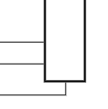
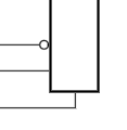
Figure 7. All ports have polarity
high
Figure 7. One port has low polarity
Section
3:
In
section 3, you have access to individual options for each module
(some modules duplicate options). We generally distinguish a few setting
options/objects for all modules:
|
|
Short
Description
|
|
|
input
integer value for bus width
|
|
|
choose
SET input mode: synchronous or asynchronous
|
|
|
choose
CLR input mode: synchronous or asynchronous
|
|
|
all
buses will be generated as split signals
|
|
|
you
are able to change selected module type (from VCC to GND, from AND to OR,
hot2bin to bin2hot, minimum to maximum, etc.)
|
|
|
for
(de)multiplexers you can change code style generation from ?case statement?
to ?one I input bus?, additional RAM (vendor XILINX) can be generated with
multiplexer or 3-state buffer code style
|
|
|
indicates
how many input buses will be generated with actual data width
|
|
|
there
are available changes to count direction (up/down/updown), shifting (right/left/rightleft)
|
|
|
choose
module arithmetic mode between ?adder-subtracter-add/sub?, ?arith-logic-arith/logic?
|
|
|
indicates
input / output data format (signed, unsigned)
|
|
|
option
is available only for Basic Counter, type Modulo, represents counter value
when counter is cleared
|
|
|
option
is available only for Basic Counter, type BCD, generated code has split
BCD decades
|
|
|
count
of RAM cells
|
|
|
data
width
|
|
|
count
of memory cells (FIFO/LIFO)
|
|
|
by
default there is set 2, in this case there is active output AE in range
from 1 to 2 (FIFO/LIFO)
|
|
|
by
default there is set 14 and Depth 16, in this case there is active AF output
in range from 14 to 15 (FIFO/LIFO)
|
|
|
indicates
input data width (SDA FIR)
|
|
|
indicates
output data width (SDA FIR)
|
|
|
|
|
|
coefficient
values are converted to Coefficient Width bus
|
|
|
count
of Coefficient Values
|
|
|
count
of remember and researched (to find the minimum or maximum value) cells
|
|
|
count
of BCD counter decades
|
Entry Names;
You
cannot enter VHDL and Verilog languages or reserved
words. Otherwise, IP CORE Generator will display
an error message while you move
the cursor from the actual
entry box. The
following figure presents an example of input error message:
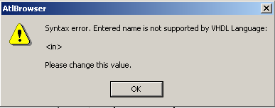
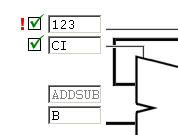
Additionally,
an exclamation mark in
red is displayed to suggest that
the port name
be corrected:
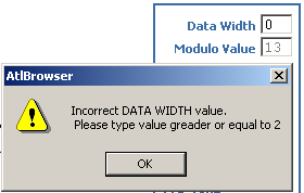
Entry Values;
Each
module has an individual
data width range. All input boxes in section 3 figure 4 can get only numeric
values. Please refer to module help. If you type the wrong
data width, an
error will automatically be displayed.