![]()
작성일: 2003.08.26
![]()

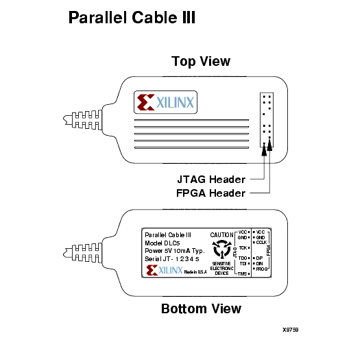
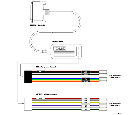
The Parallel Download Cable III consists of a cable assembly containing logic to protect your PC's parallel port and a set of headers to connect to your target system. PC III is replaced by PC IV in March 2002 with legacy support from iMPACT.
Using the Parallel Download Cable requires a PC equipped with an AT compatible parallel port interface with a DB25 standard printer connector. Figure 2-1 shows the Parallel Download Cable.
Connect the parallel cable to the host system and your target system.

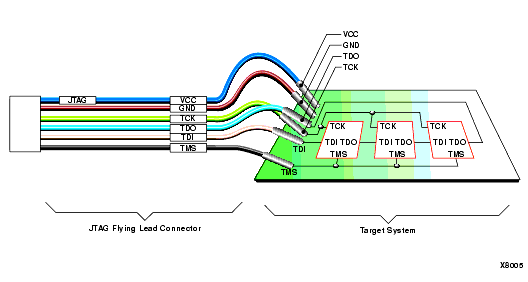
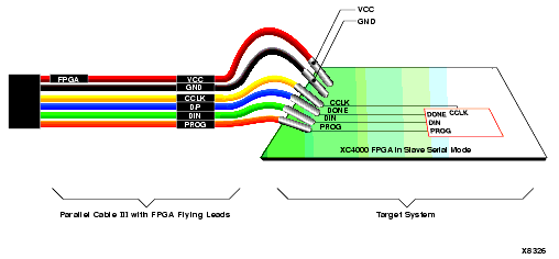
The parallel download cable can download to a single device or several devices connected in either a boundary-scan chain or a slave-serial daisy chain (FPGA only). The parallel cable can also be used to read back configuration and boundary-scan data.
The transmission speed of the Parallel Download Cable is determined solely by the speed at which the host PC can transmit data through its parallel port interface.

JTAG parallel cable schematic contains schematic diagrams of the Parallel Download Cable.
Table 2-5 Parallel Cable Connections and Definitions
| Name |
Function | Connections |
|---|---|---|
| VCC | Power - Supplies VCC (5 V, 3.3V, or 2.5V, 10 mA, typically) to the cable. | To target system VCC |
| GND | Ground - Supplies ground reference to the cable. | To target system ground |
| TCK | Test Clock - this clock drives the test logic for all devices on boundary-scan chain. | Connect to system TCK pin. |
| TDO | Read Data - Read back data from the target system is read at this pin. | Connect to system TDO pin. |
| TDI | Test Data In - this signal is used to transmit serial test instructions and data. | Connect to system TDI pin. |
| TMS | Test Mode Select - this signal is decoded by the TAP controller to control test operations. | Connect to system TMS pin. |

Table 2-6 Parallel Cable Connections and Definitions
| Name | Function | Connections |
|---|---|---|
| VCC | Power - Supplies VCC (5 V, 3.3V, or 2.5V, 10 mA, typically) to the cable. | To target system VCC |
| GND | Ground - Supplies ground reference to the cable. | To target system ground |
| CCLK | Configuration Clock --- is the configuration clock pin, and the default clock for readback operation. | Connect to system CCLK pin. |
| DONE (D/P) | Done/Program --- Indicates that configuration loading is complete, and that the start-up sequence is in progress. | Connect to system DONE pin. |
| DIN | Data In --- Provides configuration data to target system during configuration and is tristated at all other times. | Connect to system DIN pin. |
| PROG | Program --- A Low indicates the device is clearing its configuration memory. Active Low signal is used to initiate the configuration process. |
Connect to system PROG pin. |
![]()